Injection Molding Simulation Case Study: Flow Dynamics and Structural Integrity of Polymer Parts
Introduction
Injection molding is widely used in the production of complex polymer components where dimensional accuracy and material performance are critical. However, challenges such as incomplete filling, air entrapment, high localized stresses, and post-cooling deformation can compromise product quality. To address these, advanced simulations are increasingly adopted in the design phase to virtually replicate mold behavior and evaluate potential issues before fabrication.
In this study, we present a comprehensive simulation of the injection molding process for a precision housing component. The analysis integrates flow dynamics and structural behavior to provide actionable insights for optimizing part and mold design. This case highlights our team’s ability to simulate real-world manufacturing scenarios and deliver engineering solutions that improve both process reliability and product integrity.
Objective
The goal of this simulation was twofold:
Flow Behavior Analysis: To model the transient flow of a non-Newtonian polymer during cavity filling, identify potential air entrapment zones, and evaluate the impact of varying inlet pressures on flow uniformity.
Structural Stress Evaluation: To assess the residual stresses and deformation in the molded part after cooling, enabling early detection of warpage-prone regions and areas requiring design reinforcement.
The simulation outcomes informed design decisions that significantly reduced risk of defects and minimized the need for costly physical iterations
Engineering Insights
Flow Front Evolution: Accurately tracked the movement of the molten polymer front, capturing delays and directional preferences in complex cavity sections.
Pressure Mapping: Identified high-pressure zones that correlate with known defect risks such as flashing or sink marks.
Air Entrapment Prediction: Localized air pockets detected near outlets and ribs, prompting refinements in vent design.
Residual Stress Zones: Structural analysis revealed elevated stress concentrations in unsupported corners and long walls.
Deformation and Warpage: Subtle dimensional deviations were predicted due to thermal and pressure gradients — crucial for maintaining tolerance in assembled products.
Simulation Strategy
The component under study featured complex geometrical elements including thin-walled sections, bifurcated outlet tubes, and functional ribs. The simulation workflow included:
Transient multiphase flow analysis to model molten polymer displacing air during mold filling.
Shear-dependent viscosity model representing HDPE’s non-Newtonian behavior under varying flow conditions.
Time-varying inlet pressure profile that mimicked actual industrial injection cycles.
Structural mechanics coupling, where thermal and pressure data from the flow simulation were used to compute internal stresses and potential warpage.
Special care was taken to resolve high-gradient regions with localized mesh refinement for enhanced accuracy in flow and stress prediction.
Impact and Outcome
The insights generated from this simulation helped the client make data-driven design decisions:
Gate and vent positions were revised to improve flow symmetry and eliminate trapped air.
Wall thicknesses were fine-tuned to balance filling ease and mechanical stiffness.
Stress-prone features were rounded and reinforced to minimize structural weaknesses.
Cycle parameters (injection pressure, hold time) were validated digitally before physical trials.
By simulating both flow and structural behavior within the same workflow, the project achieved:
Reduced prototyping costs
Accelerated time-to-tooling
Improved product quality and consistency
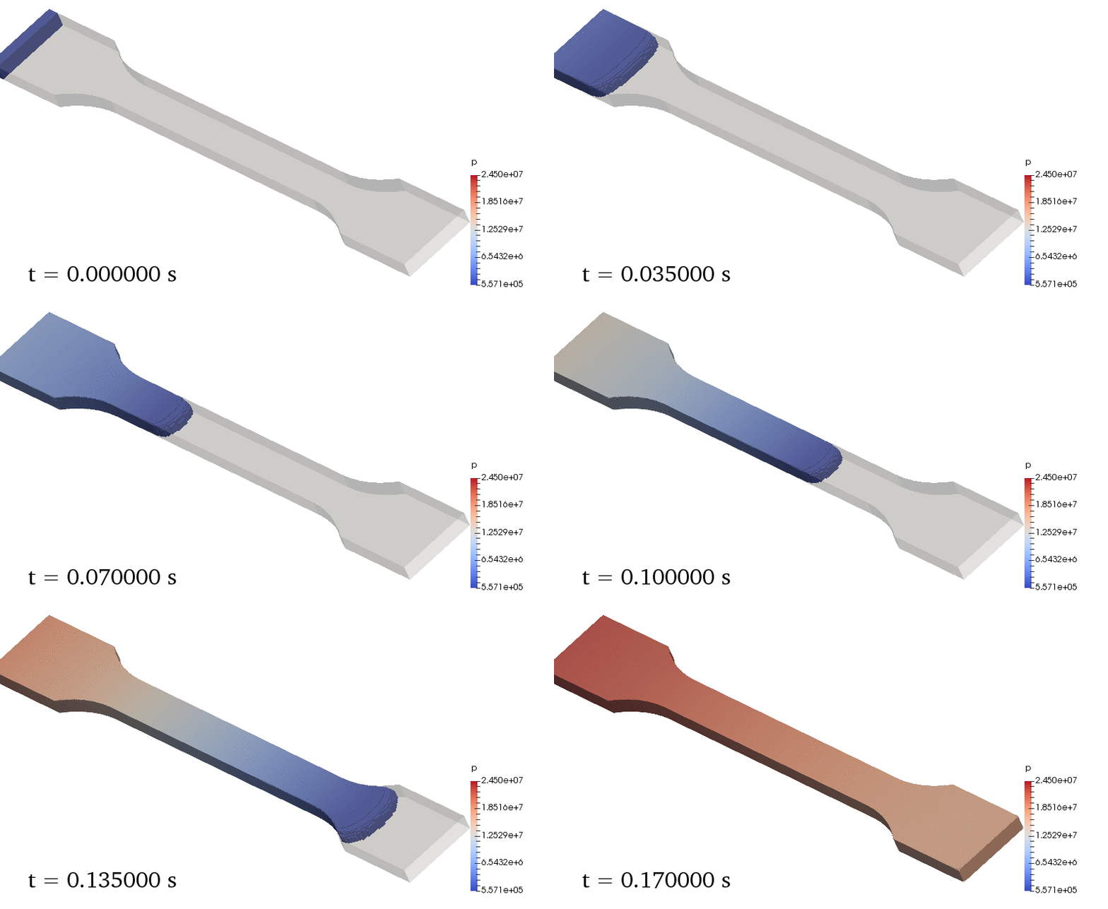
The following simulation demonstrates the transient pressure distribution during the injection molding of a dogbone-shaped polymer specimen. This animation highlights how pressure builds and propagates throughout the mold cavity over time. The red regions indicate areas of peak injection pressure, typically near the gate or at flow resistance points, while the blue regions correspond to zones experiencing lower pressure during mold filling.
This dynamic visualization complements our analysis by revealing potential locations of flow-induced stress concentration, which are critical in assessing part quality, gate design, and material performance after molding.
Conclusion
This case study reflects our capability to integrate physics-based modeling across flow and structural domains—providing complete visibility into the injection molding process. Our approach helps clients move from trial-and-error toward precision-driven, virtual validation of critical manufacturing processes.
Whether you're optimizing mold design, validating new materials, or improving production yield—our simulation solutions empower you to move faster, with greater confidence.
This simulation framework can be easily extended to include metal inserts, allowing analysis of flow behavior around embedded parts, pressure distribution at the plastic-metal interface, and structural stresses after cooling — critical for insert molding applications in the automotive and electronics industries


