Insert Mold Cooling Simulation: Optimizing Thermal Behavior of Overmoulded Components Using CFD
Introduction
Insert molding plays a critical role in the manufacturing of high-performance parts used in industries such as automotive, electronics, and electrical safety systems. These components often combine metallic inserts and thermoplastics, requiring not only dimensional accuracy but also controlled heat transfer during the injection and cooling phases.
In this case study, we simulate a flat insert injection molding configuration and analyze the temperature distribution and cooling performance of the system. The objective is to understand how the presence of a metal insert and mold wall design impacts thermal gradients, and how optimizing cooling rates can improve part quality.
This work draws inspiration from a publicly available CFD study that introduced the Variable Cooling Rate Heat Conduction Strategy (VCRHCS), a technique aimed at improving thermal balance in overmoulded parts.
Objective
Simulate the cooling process in a mold containing a central metallic insert.
Evaluate temperature gradients, cooling efficiency, and thermal lag in the insert zone.
Demonstrate how cooling strategies can be adapted to improve:
Part uniformity
Insert bonding
Cycle time optimization
Simulation Methodology
The simulation was designed to replicate a typical insert injection molding configuration, with a focus on understanding thermal behavior during the cooling phase. The key components of the geometry and boundary setup include:
1. Geometry Configuration
Flat Rectangular Mold Cavity: Representing a common industrial mold, the cavity is designed with uniform wall thickness and symmetric layout to study controlled cooling behavior.
Centrally Embedded Flat Metal Insert: The insert (e.g., aluminum or copper) is placed in the center of the mold cavity. This mimics real-world scenarios where a conductive metal is overmoulded with a thermoplastic shell.
Surrounding Thermoplastic Region: The polymer (HDPE, PP, or similar) completely encapsulates the insert, representing a fully filled cavity at the start of the cooling phase.
Dimensions: The overall cavity dimensions are sized to reflect a practical test part used in electronic housings or sensor enclosures.
2. Material Properties Assigned
Metal Insert:
High thermal conductivity (e.g., aluminum: ~200 W/m·K)
High density and specific heat
Acts as a heat sink, retaining and transferring heat during early cooling stages
Polymer Region:
Lower thermal conductivity (~0.2 W/m·K)
Lower density and higher thermal resistance
Prone to non-uniform cooling and surface defects if unmanaged
This difference in thermal properties leads to temperature gradients and potential bonding issues at the metal-polymer interface.
3. Mold Wall Boundary Conditions
Adjustable Cooling Profiles: The study explores both uniform and zone-based cooling strategies (VCRHCS).
Uniform cooling applies the same temperature across all mold walls.
Variable cooling zones apply lower temperatures near the insert area and higher temperatures elsewhere to achieve thermal balance.
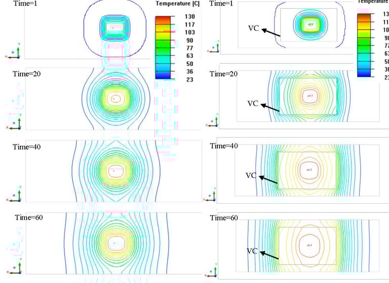
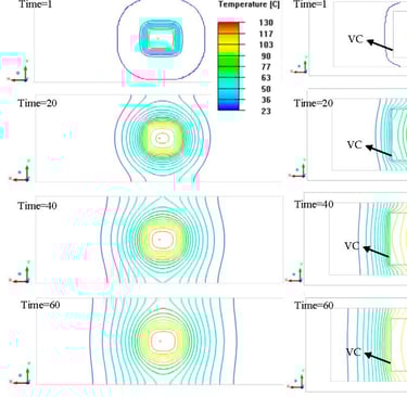
Cooling Duration: The simulation runs over a transient period (2 to 10 seconds), capturing how temperature decays across the entire domain.
4. Initial and Boundary Conditions
The entire cavity (insert + polymer) is initialized at a typical melt temperature (e.g., 240°C).
Mold walls are cooled to controlled values (e.g., 25–60°C).
Heat conduction is modeled without internal fluid motion (solid-state transient thermal simulation).
Why This Setup Matters
Accurately replicates real-world insert molding scenarios where uneven cooling causes internal stress and bonding failure.
Allows engineers to assess the effectiveness of cooling channel placement or conformal cooling strategies in high-precision molding tools.
Helps in reducing cycle time and improving dimensional stability of overmoulded products.
Challenges in Insert Molding
1. Thermal Mismatch
Metals like aluminum and copper have significantly higher thermal conductivity than polymers. This causes them to retain heat longer, potentially leading to:
Slow solidification in adjacent plastic zones
Stress accumulation at the plastic-metal interface
Sink marks or surface blemishes
2. Uneven Cooling
Using a uniform cooling temperature across the mold may:
Cool thin wall areas too quickly
Leave thicker insert regions hotter
Result in residual stress and part distortion
3. Interface Quality
Improper thermal control can cause:
Poor polymer wetting on insert surfaces
Weak adhesive or mechanical bonding
Delamination during field operation (especially in automotive)
Engineering Strategy: Variable Cooling Zones
The simulation implemented a Variable Cooling Rate Heat Conduction Strategy (VCRHCS) — a zonal cooling technique that applies different temperatures to different mold wall regions.
Why it works:
Hot zones around the insert are cooled more aggressively
Cooler zones around edges slow down, achieving thermal equilibrium
Enhances bond formation and minimizes internal stress
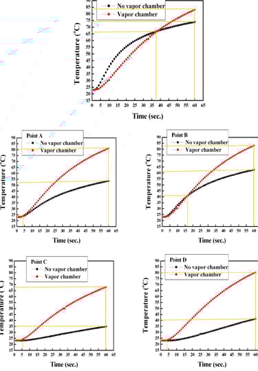
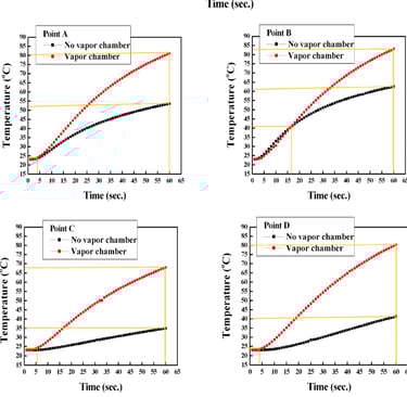
Key Results
Insert Region Cooling Delay: The metal retained heat longer, affecting nearby polymer regions.
Thermal Gradients Balanced: With VCRHCS, the temperature difference between core and edge reduced substantially.
Improved Uniformity: Lower residual stress risk and better part stability post-ejection.
Cycle Time Optimization: Achieved desired thermal targets faster without compromising bond quality.
Why This Matters for Manufacturers
Shorter Time to Market: Fewer physical trials required during tool development.
Cost Savings: Reduce rework caused by poor insert bonding or visual defects.
Improved Reliability: Consistent thermal profiles lead to predictable performance in the field.
Better Aesthetics: Controlled cooling avoids warpage and surface marks.
Conclusion
This simulation study highlights the critical role of customized cooling strategies in optimizing insert molding processes. Unlike conventional uniform cooling, the Variable Cooling Rate Heat Conduction Strategy (VCRHCS) ensures more balanced thermal distribution, particularly around embedded metal inserts. This leads to improved bonding strength, reduced thermal gradients, and lower residual stress in overmoulded components.
By implementing a CFD-based virtual validation step, manufacturers can simulate and predict the thermal behavior of both the polymer and the insert before committing to physical trials. This proactive approach allows for:
⚙️ Optimized mold design that minimizes the risk of warpage and sink marks
💡 Insightful decisions on cooling channel placement, cycle time tuning, and zone-based wall temperature control
🕒 Shorter development cycles by reducing dependency on repeated prototyping
✅ Consistent part quality in high-precision applications such as sensors, switch housings, and safety enclosures
At AnukaranAI, we specialize in delivering advanced simulation solutions that bridge design and manufacturability. Whether you're working with high-conductivity inserts, multi-material assemblies, or mission-critical tolerances, our expertise in CFD and FEA integration helps you:
🔍 Predict mold behavior under real-world thermal and structural loads
🌐 Validate cooling and filling strategies virtually before mold fabrication
🧠 Identify failure-prone zones and optimize for long-term reliability
🔄 Reduce scrap rates and tooling changes by building insight into your process early on
Insert molding isn't just about combining materials — it's about synchronizing flow, temperature, and structure in real time. With our tailored simulation workflows, you can gain this control digitally and ensure every component meets its performance requirements from day one.